
Analog Circuits

Lesson 1.5: Ohm's Law Revisited: Impedances
If you couldn't tell, I was dying to get to this part. I gave you a pretty short version of what the current-voltage relationships are, so you could see how hard they can be to remember! I'll show you where the complex number representation comes from, first. Then, we'll talk about why representing everything as impedances can make circuit analysis much easier!
The mathematical foundations
We're allowed to get away with turning all our calculus into algebra, because of the Fourier Transform. It says that any signal, no matter how random, can be decomposed into sums of sines and cosines. From there, we can use Euler's formula
\( e^{j \omega t} = \cos{(\omega t)} + j \sin{(\omega t)} \)
to transform all our signals into complex numbers. So we're representing all the signals as this single number, \( e^{j \omega t} \).
If you take the time derivative of \( e^{j \omega t} \), you get \( j \omega \cdot e^{j \omega t} \). Don't forget, \( \omega = 2 \pi f \), where \( \omega \) is the frequency measured in \( rad / s \), and \( f \) is the frequency measured in \( Hz \).
Guess what else is cool? Because the Laplace Transform and the Fourier Transform are basically equivalent, you can make the substitution \( s = j \omega \) to save some writing. (Also, it's a little easier to remember frequency is actually a single variable that way.)
We call this variable \( s \) an s-parameter.
The impedance formulas
This one will knock your socks off.
You can analyze circuits using s-parameters to get solutions for both DC and AC conditions simultaneously.
It boils down to two steps. You can omit the second step if you want to know the
AC behavior at reasonable frequencies (around \( 1 kHz \) up to around \( 1 MHz \)).
- Analyze the circuit using s-parameters.
- Take the limit s → 0 (dc) or s → ∞ (high-frequency ac).
Now, I'm sure you're asking, "Well, how the heck can you do that?".
We're going to use a generalization of Ohm's Law. If you remember how it was defined, we didn't actually say whether we were using the real numbers \( \mathbb{R} \) or the complex numbers \( \mathbb{C} \) to define the resistance. Resistance is actually defined in the real numbers.
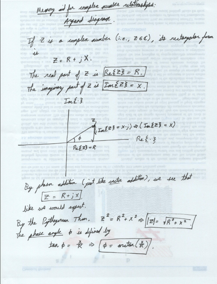
Impedances are a generalization of "resistance" to the complex numbers. They're usually written in this general form. \( Z \) is the impedance, \( R \) is the real part of the impedance, and \( X \) is the imaginary part of the impedance. \( R \) is called the resistance, like before. \( X \) is called the reactance.
\( Z = R + j X \)
We can write any arbitrary complex number in two forms: rectangular or polar. There are two subsets of the polar form: the exponential and magnitude/angle forms.
Rectangular: \( R + j X \).
Polar exponential: \( |Z| e^{j \phi} \).
Polar magnitude/angle: \( |Z| \angle \phi \).
You get to the polar forms from the rectangular form through these formulas:
\( |Z| = \sqrt{R^2 + X^2} \).
\( \phi = \arctan(\frac{X}{R}) \).
Remember that nice idea from up above? \( [ \frac{d}{dt}(e^{j \omega t}) = (j \omega) \cdot
e^{j \omega t}. ] \) If you want to take a time derivative of a complex number, you just multiply
by \( j \omega \).
Now we can use it to convert our current-voltage equations for capacitors and inductors into
impedance form. For a capacitor, we had \( I = C \frac{dV}{dt} \). If we assume both the
current and the voltage are complex numbers, we get
\( I = j \omega C V \).
after using our time derivative rule. If you do a similar thing for the inductor equation, you get
\( V = j \omega C I \).
If we use Ohm's Law for an arbitrary impedance, \( V = Z I \), we can see immediately that
\( Z = \frac{V}{I} \).
So that's the definition of impedance. We'll need to get our formulas in this form if we want to see what the impedances really are. For a capacitor, we end up with
\( Z = \frac{1}{j \omega C} (= \frac{- j}{\omega C}) \).
An inductor's impedance formula is
\( Z = j \omega L \).
I'll apply \( s = j \omega \) next, to write these in a more compact format. Finally,
\( Z = \frac{1}{s C} \) (capacitor), and
\( Z = s L \) (inductor).
You can use these to figure out how your circuit behaves without having to take derivatives. Cool, huh?
Bottom line. \( Z = R \) for a resistor, \( Z = \frac{1}{s C} \) for a capacitor, and \( Z = s L \) for an inductor. If you want to know how the circuit responds to DC input, take the limit of your final answers as \(s \rightarrow 0 \). If you want to see how the circuit responds to super-high frequencies, take the limit of your final answers as \( s \rightarrow \infty \). Lastly, if you need the behavior at a specific frequency \( f \), set \( s = j 2 \pi f \) and shove it into your calculator.
If you found this content helpful, it would mean a lot to me if you would support me on Patreon. Help keep this content ad-free, get access to my Discord server, exclusive content, and receive my personal thanks for as little as $2. :)
Become a Patron!